Lab task 1
Deadline: week 6 (for students coming in even week labs) and week 7 (for students coming in odd week labs)
For this lab you need to implement :
- the first phase of the video encoder: dividing the image into blocks of 8x8 pixels
- the last phase of the video decoder: composing the image from a set of 8x8 pixels blocks
The encoder part:
You should do the following tasks:
- read the PPM image and convert each pixel value from RGB to YUV (use the arithmetic equations from the
slides of the course)
- form 3 matrixes: one for Y components, one for U components and one for V components
- divide the Y matrix into blocks of 8x8 values; for each block store: the 64 values/bytes from the block, the type of block (Y) and the position of the block in the image
- divide the U and V matrixes into blocks of 8x8 values; each block stores: 4x4=16 values/bytes from the block
(i.e. perform 4:2:0 subsampling, that is for each 2x2 U/V values store only one U/V value which should be the average of those 2x2=4 values), the type of block (U or V) and
the position of the block in the image
- store the list of 8x8 Y blocks and 4x4 U and V blocks and print this list on the screen (to see it it is correct)
The decoder part: for this part you should do the opposite of the above steps, i.e. starting from a list of 8x8 Y-values blocks
and subsampled 4x4 U- and V-values blocks you should compose the final PPM image and display it on a canvas/form.
The test image you can use for the first lab is here (PPM-P3 format) or here (PPM-P6 format).
It is the same image written in a simple RGB file format called PPM. More details about the PPM format can be found
here. This file format contains a small header of 3 lines (or more if there are
comments - line which start with '#') specifying:
- the format: P3 (each pixel has 3 bytes, one for Red, one for Green, one for Blue and these bytes/numbers are written on separate lines as ASCII strings)
or P6 (each pixel has 3 bytes, one for Red, one for Green, one for Blue and these bytes/numbers are binary written into the file)
- the resolution of the image: width and height in pixels
- the maximum value of a byte component (red or green or blue): usually 255
After this header data bytes follow for each pixel in the image, starting from the top-left corner of the image, in ASCII format if P3 format is used
or in binary format if P6 format is used.
Lab task 2
Deadline: week 8 (for students coming in even week labs) and week 9 (for students coming in odd week labs)
For this lab you need to implement :
- the second phase of the video encoder: performing Forward DCT (Discrete Cosine Transform) and then Quantization on an 8x8 pixels block
- the last but one phase of the video decoder: performing the DeQuantization and the Inverse DCT (Discrete Cosine Transform) on 8x8 pixels blocks
The encoder part:
YCbCr Conversion, Block splitting & Subsampling
8x8 Y/Cb/Cr blocks
... ... ...
FDCT (Forward Discrete Cosine Transform)
8x8 DCT blocks
... ... ...
8x8 quantized blocks
...
8x8 quantized blocks
...
8x8 quantized blocks
Forward DCT (Discrete Cosine Transform) takes as input an 8x8 Y/Cb/Cr values block and
transforms this block intro another 8x8 DCT coefficient block. Please note that in the "YCbCr Conversion, Block splitting &
Subsampling" phase you did for lab 1, you produced 8x8 Y blocks and 4x4 Cb/Cr blocks. For the DCT, you need to transform the
4x4 Cb/Cr blocks back to 8x8 matrixes, so that a single Cb/Cr value is placed in 4 distinct places in the 8x8 matrix (i.e. you
do the reverse of subsampling).
Before applying the Forward DCT, you should substract 128 from each value of every 8x8 Y/Cb/Cr block.
The forward DCT should be implemented using the following formula:
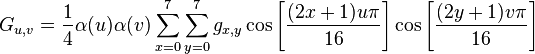
where gx,y is the Y/Cb/Cr value from coordinates "x" and "y" in the input 8x8 Y/Cb/Cr block (0 ≤ x ≤ 7, 0 ≤ y ≤ 7)
and Gu,v is the DCT coefficient from coordinates "u" and "v" in the resulting 8x8 DCT block (0 ≤ u ≤ 7, 0 ≤ v ≤ 7).
α(u) is 1/sqrt(2) if u=0 and 1 if u > 0.
Quantization phase takes as input an 8x8 block of DCT coefficient and divides this block
to an 8x8 quantization matrix obtaining an 8x8 quantized coefficients block. Use the following quantization matrix:
                6   4   4   6   10  16  20  24
                5   5   6   8   10  23  24  22
                6   5   6   10  16  23  28  22
        Q =     6   7   9   12  20  35  32  25
                7   9   15  22  27  44  41  31
                10  14  22  26  32  42  45  37
                20  26  31  35  41  48  48  40
                29  37  38  39  45  40  41  40
The division is performed component-wise (i.e. DCT[x][y] is divided to Q[x][y]) and it is
integer division - keep only the quotient, loose the remainder.
The decoder part:
8x8 quantized blocks
...
8x8 quantized blocks
...
8x8 quantized blocks
8x8 DCT blocks
... ... ...
IDCT (Inverse Discrete Cosine Transform)
8x8 Y/Cb/Cr blocks
... ... ...
RGB Conversion, Image creation from 8x8 RGB blocks
DeQuantization phase is the opposite of quantization; takes as input an 8x8 quantized block produced by the encoder and
it multiplies this block (component-by-component) with the 8x8 quantization matrix outlined above.
Inverse DCT (Discrete Cosine Transform) is the opposite of Forward DCT used by the encoder; it takes
a 8x8 DCT coefficients block and it produces an 8x8 Y/Cb/Cr block. The inverse DCT should be implemented using the following formula:

where fx,y is the Y/Cb/Cr value from coordinates "x" and "y" in the resulting 8x8 Y/Cb/Cr block (0 ≤ x ≤ 7, 0 ≤ y ≤ 7)
and Fu,v is the DCT coefficient from coordinates "u" and "v" in the input 8x8 DCT block (0 ≤ u ≤ 7, 0 ≤ v ≤ 7).
α(u) is 1/sqrt(2) if u=0 and 1 if u > 0.
After you apply the Inverse DCT, do not forget to add 128 to each value of every 8x8 Y/Cb/Cr block obtained.
Lab task 3
Deadline: week 12 (for students coming in odd week labs) and week 13 (for students coming in even week labs)
For this lab you need to implement :
- the third phase of the video encoder: performing Entropy Encoding (only ZigZag parsing and run-length encoding, NOT Huffman encoding)
- the first phase of the video decoder: performing Entropy Decoding (only run-length decoding and forming an 8x8 block by zig-zag parsing)
The encoder part has as input the lists of Y/Cb/Cr 8x8 blocks
produced by the Quantizer from lab2 and as output a vector of bytes.
From each 8x8 block (either Y or Cb or Cr) the encoder obtains a vector of maximum 64*3-1 bytes in the following way:
- the block is first parsed in zig-zag order as depicted in the following image
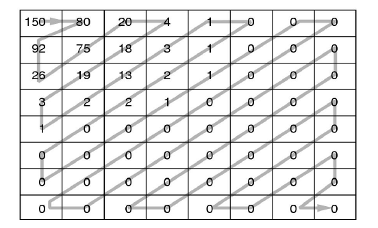
resulting an array of coefficients like this one:
150, 80, 92, 26, 75, 20, 4, 18, 19, 3, 1, 2, 13, 3, 1, 0, 1, 2, 2, 0, 0,
0, 0, 0, 1, 1, 0, 0, 0, 0, 0, 0, 0, 0, 0, 0, 0, 0, 0, 0, 0, 0, 0, 0, 0,
0, 0, 0, 0, 0, 0, 0, 0, 0, 0, 0, 0, 0, 0, 0, 0, 0, 0, 0.
- the DC coefficient (i.e. the first value; e.g. 150) of this array is encoded in 2 bytes:
(SIZE) and (AMPLITUDE) where AMPLITUDE is the actual value of the coefficient (i.e. 150) and
SIZE is the number of bits necessary in order to represent AMPLITUDE according to the
following table:
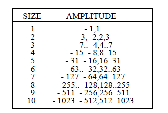
In our example SIZE is 8 because 150 is between 128 and 255.
- the remaining 63 AC coefficients of the block are encoded in the following way:
- an AC coefficient with the value zero is skipped (is not encoded at all)
- a non-zero AC coefficient is encoded in 3 bytes: (RUNLENGTH,SIZE)(AMPLITUDE)
where RUNLENGTH is the number of consecutive zeroes that occur in front of this AC coefficient
and SIZE and AMPLITUDE are the same as the ones defined for the DC coefficient above.
- if the block ends with a consecutive sequence of zeroes, all these zero coefficients
are skipped and instead of them we place the bytes (0,0) (2 bytes, END-OF-BLOCK code)
in the encoders output.
For example, for the block depicted above, the output of the entropy encode would be:
(8)(150), (0,7)(80), (0,7)(92), (0,5)(26), (0,7)(75), (0,5)(20), (0,3)(4), (0,5)(18), (0,5)(19),
(0,2)(3), (0,1)(1), (0,2)(2), (0,4)(13), (0,2)(3), (0,1)(1), (1,1)(1), (0,2)(2), (0,2)(2), (5,1)(1), (0,1)(1), (0,0)
You should first encode the first 8x8 Y block of quatized coefficients
and place them in the output byte array, then encode the first 8x8 Cb block of quantized coefficients and then the first
8x8 Cr block of quantized coefficients and place them in the output byte array, then encode the 2nd 8x8 Y block of
the image and the 2nd 8x8 Cb block of the image and the 2nd Cr 8x8 block of the image and so on ...
The decoder part has as input an array of bytes and as output
the lists of 8x8 blocks of quatized Y/Cb/Cr coefficients. This list of 8x8 blocks of quatized Y/Cb/Cr coefficients
is then passed to the DeQuantizer built in lab2.
In order to read an 8x8 block of Y/Cb/Cr coefficients, the decoder must:
- read first 2 bytes corresponding to the DC coefficient
- read maximum 63 tuples (RUNLENGTH,SIZE)(AMPLITUDE) for each AC coefficient of the block or until
a set of 2 consecutive zeros (0,0) is found in the input array